

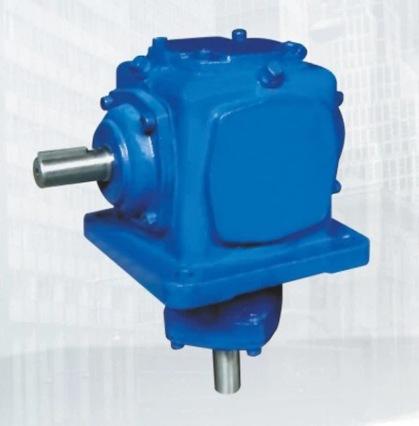

Speed Reducer Gearbox
A speed reducer gearbox (also called a reduction gearbox) is a mechanical system that reduces the input speed from a motor or engine while increasing torque at the output. These gearboxes are widely used in industrial machinery, automotive systems, robotics, and power transmission applications.
Key Components of a Speed Reducer Gearbox
Gears – The primary elements that transmit motion and reduce speed.
Spur gears – Simple, cost-effective, but noisy.
Helical gears – Smoother and quieter than spur gears.
Bevel gears – Used for right-angle speed reduction.
Worm gears – High reduction ratios, self-locking capability.
Planetary gears – Compact, high torque, and efficient.
Input & Output Shafts – Connect to the motor (input) and driven equipment (output).
Housing – Protects internal components from contamination and damage.
Bearings – Support shafts and reduce friction.
Seals & Lubrication – Prevent leakage and ensure smooth operation.
Types of Speed Reducer Gearboxes
Type Characteristics Common Applications
Helical Gearbox Smooth, quiet, efficient Conveyors, mixers, extruders
Worm Gearbox High reduction, self-locking, compact Lifts, conveyors, packaging
Planetary Gearbox High torque, compact, high efficiency Robotics, CNC machines, aerospace
Bevel Gearbox Right-angle power transmission Automotive differentials, mills
Cycloidal Gearbox High reduction, shock load resistance Robotics, heavy machinery
How a Speed Reducer Works
Input Power – A motor provides high-speed, low-torque input.
Gear Reduction – Gears mesh to reduce speed while multiplying torque.
Output Power – Delivers lower speed and higher torque to the load.
Gear Ratio Formula:Gear Ratio=Input Speed (RPM)Output Speed (RPM)Gear Ratio=Output Speed (RPM)Input Speed (RPM)
Torque Increase:Output Torque=Input Torque×Gear Ratio×Efficiency
Output Torque=Input Torque×Gear Ratio×Efficiency
Reduction Ratio – Required speed decrease.
Torque Capacity – Must handle load demands.
Efficiency – Helical & planetary gearboxes are most efficient (~95%+).
Mounting Style – Foot-mounted, flange-mounted, shaft-mounted.
Backlash – Precision applications (e.g., robotics) need low backlash.
Environment – Sealed units for dusty/wet conditions.

Applications
Industrial Machinery – Conveyors, crushers, mixers.
Automotive – Transmissions, differential systems.
Robotics – Precision motion control.
Wind Turbines – Speed reduction for generators.
Aerospace – Actuators, landing gear systems.
Would you like recommendations for a specific application?
Hot Tags: speed reducer gearbox, China speed reducer gearbox manufacturers, suppliers, factory, hv motors, the universal motor, high voltage motor, electromagnetism electric motor, geared motor, ac induction motor single phase
You Might Also Like


Send Inquiry